When I got my advanced class license in 1969, I replaced my Heathkit DX-60 with an E F Johnson Viking Ranger. K7NSW read that I had used the Ranger and a National NC-300 receiver. He VERY GENEROUSLY gave me a Ranger, an NC-300, an Astatic D-104 microphone on a T-UG9 stand, a Johnson 250-888-1 microphone, and a Johnson Matchbox tuner.
Integrating Vintage Equipment
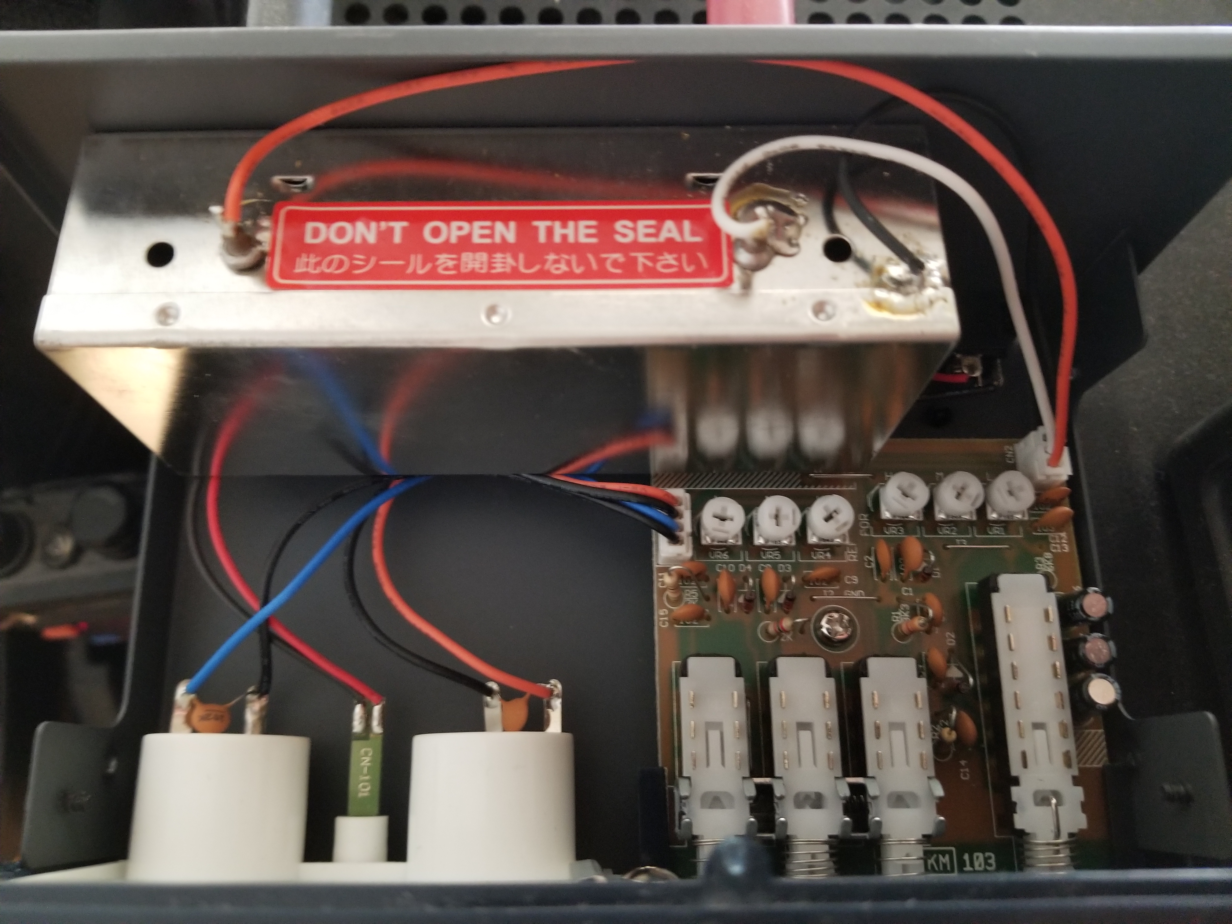
As shown in the block diagram here, the vintage transmitter and receiver are switched into the RF chain using an MFJ 4712 RF relay. This relay is designed to remotely switch between two antennas. The remote control is achieved by adding a 12 VDC signal to the coax between the control box and the remote relay to select antenna 2. Here, the remote relay selects which "transceiver" drives the CN-501H wattemter on the input to the Dentron Clipperton L amplifier. The remote box is left in the "Antenna 2" position, causing the Ranger/NC-300 to be connected to the wattmeter and amplifier. The remote box is powered by an external 12 VDC power supply. That power supply is plugged into a switched outlet strip along with the Ranger and the NC-300. When that power strip is turned on, the Ranger and the NC-300 receive power, and the RF relay switches the amplifier input to the Ranger and NC-300. When the power strip is off, the vintage equipment is shut down, and the RF relay connects the SEA 245 to the amplifier.
Of course, the RTTY equipment here is also vintage. For more information on that, see RTTY Notes. Back in high school, I dug into the Ranger VFO and modified it to run FSK for RTTY. I'm not doing that modification now.
Viking Ranger
The Ranger powered up and appeared ready to go. I found, however, that the VFO oscillator would not reliably start. Upon opening the VFO enclosure, I found the filament was not lit on the osciallator tube. Some DeoxIT was applied to the tube socket, the tube reinserted a few times, and all was well.
Operating the Ranger on 40 meters AM, the VFO frequency was very unstable. The frequency varied with PA tuning leading me to suspect the 0A2 regulator tube since varying PA current would affect the voltage on the high voltage supply due to loading.. However, the tube was glowing, and measuring the oscillator screen voltage showed it was steady with varying PA tuning. It was noted that only the oscillator screen is regulated, not the plate voltage. The Ranger was connected to a Variac autotransformer, and the line voltage varied over a large range while watching the transmit frequency. The variation was very minor when compated with the variation due to PA tuning. It was noted that several of the sheet metal screws that attach the left side (as viewed from the front of the Ranger) of the VFO enclosure were missing. Perhaps insufficient shielding was allowing RF from the power amplifier to feed back into the VFO making a high power oscillator instead of a VFO driving an amplifier. Tuning the PA would vary the tuning of this "power oscillator." The missing screws were added (#4 x 1/4 inch sheet metal screws). The frequency instability went away!.
This feedback from the PA to the VFO was also discovered by W8JI and discussed here. While VFO shielding is not mentioned, it is pointed out that the indirect grounding of the PA tuning capacitor leads to feedback. The inductance of the lead from the capacitor rotor to ground results in the capacitor rotor having RF on it, which is then carried by the capacitor shaft towards the VFO. As suggested in the article, I replaced the back top insulating washer mounting the PA tuning capacitor with a metal washer.
The Ranger had been modified as per the manual to add a PTT relay. Pairs are brought out from that relay to mute the receiver and to enable the amplifier when in transmit. The contacts that close on transmit are wired in parallel with SSRs driven by the SEA 245 PTT and fan control so either the Ranger or the SEA 245 can enable the amplifier. The relay contacts that are closed in receive are connected between the right two receiver mute terminals (standby and ground) to unmute the receiver when we are not transmitting. The receiver then mutes when we are transmitting AND the receiver front panel transmit/receive switch is in transmit. The receiver can be unmuted while in transmit (for frequency spotting, etc.) by setting the TR switch on the receiver to receive.
Audio Distortion
The CN-501H has a circuit for detecting forward and reflected power that outputs a DC voltage proportional to the square root of the forward or reflected power. Since the meter can detect peak power, the DC output follows the envelope of the RF signal. I added a couple BNC jacks to the CN-501H, one on the forward power DC output sample, and the other on the reflected power DC sample. The inside of the CN-501H is shown here. The red wire is the forward sample, and the white wire is the reflected sample. The images at the right show the forward sample driving a scope.
With mo modulation, there are 783 mV. A Reed R8090 microphone calibrator was held in front of the microphone, and the Ranger audio control adjusted to yield fairly high modulation without clipping on the negative peaks. There is pretty severe clipping on the positive peaks. Ignoring carrier shift, the positive peaks are clipping at (1.08 V - 0.783 V)/0.783 V = 8% modulation, while the negative peaks are not clipping and are modulating to (783 mV - 152 mV)/783 mV = 80%. This could be severe imbalance between the modulator tubes, which could be checked by swapping them, or, more likely, a weak final amplifier tube that cannot make it to peak power.
Joe "not a hoarder", K3TYE, generously supplied me with a few 6146 tubes to try. The table below shows the test results. In each case, the transmitter was run into a dummy load and the Reed R8090 microphone calibrator was held in front of the microphone.
| Tube Number | No Modulation Sample mV | Negative Peak Sample mV | Positive Peak Sample mV |
|---|---|---|---|
| 1 | 582 | 120 | 908 |
| 2 RCA 6146A | 604 | 52 | 1080 |
| 3 | 583 | 100 | 910 |
| 4 Original | 560 | 60 | 492 |
The audio doesn't sound too bad. Here's a recording of the Viking Ranger driving the Dentron Clipperton L with
carrier power of about 400 watts on 40 meters. The recording is from the
Utah web SDR.
Note that the negative modulation peaks also do not look sinusoidal. This is a common problem for diode-based envelope detectors. See a complete discussion here.
Johnson Viking Ranger Resources
- Manual
- AA8V Ranger Notes - Extensive documentation and photographs of a beautifully restored Ranger.
- W8JI Ranger Page
- W8JI Grounding PA Tuning Capacitor - Prevent feedback from PA to VFO by providing short grounding path for the PA tuning capacitor. Reaching the capacitor mounting screws in this very crowded chassis is difficult, so I only replaced the top insulated washer at the back of the tuning capacitor with a metal washer. This should properly ground the capacitor rotor. I left the previous long ground wire in place. This, along with putting all the screws in the VFO shield seems to have solved the frequency stability problem.
- W8JI Ranger Audio Modifications - Extensive documentation largely saying "Leave it alone."
- 6146 Family of Vacuum Tubes - Warns against using 6146B. Original 6146 and 6146A are good.
National NC-300 Receiver
The receiver worked as received with no modifications required, and only a simple adjustment. The drum that makes the frequencies for each band visible when that band is selected on the band switch had shifted so the wrong band (or nothing at all) was visible on each band. This was corrected as per the manual.
National NC-300 Resources

The vintage equipment operating position

Sampler output with no modulation. Note the mean is 783 mV.

Sampler output with 1 kHz modulation. Positive peakes are severely clipped.

Sampler outout using RCA 6146A (tube #2) into dummy load. Still not perfect, but clipping is less than above.